|
|
|
Polymer
Rheology
|
|
From tensor maths to practical benefits for processors & end users alike |
|
Dr.
Don Fleming
|
|
Fleming
Polymer Testing and Consultancy
|
| This
paper discusses how rheology can be used to power flow simulation techniques
for the prediction of polymer flow in real industrial processes. The ability
to simulate production behaviour, instead of committing to a time intensive
pilot plant study to actually measure it, can save a significant amount
of time and money. Computing power and the continuing quest to further our
understanding of how complex flow regimes interact, have greatly enhanced
our ability to achieve this. Using rheological measurements in concert with
flow simulation techniques it is now possible to predict a host of flow
consequences, in both 2D and 3D, in a broad range of dies, from simple rheometer
geometries to complex cable coating.
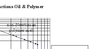
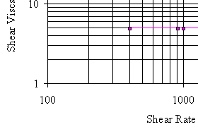
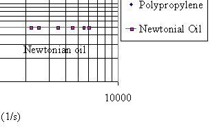
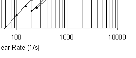
INTRODUCTION The manner in which a material deforms is also important, and this is especially true when the materials are polymers. Most of our polymer products begin life as solid pellets, and under the action of heat, are converted to a molten form whereby they can be readily squashed through a die resembling the geometry of the product we desire. It soon becomes apparent that the way in which a polymer resists deformation is intrinsic to its suitability to processing. Resistance to deformation is more commonly termed viscosity, thus if a material has a high viscosity we can expect difficulty in deforming it to the required shape, and by implication, if it exhibits a low viscosity, the subsequent forces encountered will be more favourable. It is apparent then that the ability to measure the viscosity of a material is beneficial to our expectation of process performance. To this end we use rheometers, and for the purpose of this paper, the rheometer of choice is the capillary rheometer. The capillary rheometer is essentially a ram extruder, whereby a piston is accurately driven down a high precision, heated, bore. Inside the bore is the molten polymer, and under the action of the driven piston, the melt is expressed through a die of known geometry. Pressure is measured prior to the die entry, allowing all of the parameters required for the calculation of viscosity to be recorded. On measuring the viscosity of a polymer melt it is abundantly clear that it departs from that of traditional fluids, in that its viscosity changes with deformation rate. Figure 1 shows the viscosities measured when subjecting an oil and a polymer to a typical capillary rheometry test. |
|
Figure
1
Viscosity
functions of a typical polymer melt and a Newtonian oil
|
|||||||||
|
|
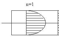
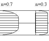
It is clear that the viscosity of the oil remains constant over the deformation range, whereas the viscosity of the polymer reduces. Consequently, the viscosity of the polymer melt is dependent on the deformation rate and is more usefully termed viscosity function. The constant, or rate independent, viscosity of the oil is termed Newtonian and that of the rate dependent polymer, shear thinning or pseudoplastic. This shear thinning behaviour of course works in the processors favour, since the rise in pressure due to increasing output, will be lower than a Newtonian material at the same output. It is at this point that we have to ask ourselves why the material is apparently working for us in reducing its viscosity, and the answer to this question lies in molecular architecture. As we know, polymers are made up of a complex arrangement of chains, and these chains, in the molten form at rest, have a multitude of orientations. However, once a polymer melt is encouraged to flow, the random orientation enjoyed at rest is broken, and the chains are forced to line up in the direction of flow. This orientation gives rise to what we refer to as an anisotropic microstructure. That is, we find that the properties of the polymer are now different in different directions, unlike a Newtonian fluid where the properties are equal in each direction (isotropic). Consequently, as the degree of alignment increases, we find that the resistance to shear flow reduces. By implication, molecular chain length (measured as weight average molecular weight, ) and length distribution (molecular weight distribution, MWD), the presence of side chain branching and secondary side chain branching, filler type, content and aspect ratio, all influence alignment and thus viscosity. At this juncture it is useful to remind ourselves that polymer melts are also elastic, and once an elastic material is forced to undergo a flow induced alignment, it will try to return to its original state. Once again, the anisotropic microstructure influences this behaviour, and it is found that restoring forces will be established in the direction of flow. The consequence of elasticity in melt flow is often manifested as die swell. Hence, a flowing viscoelastic polymer melt is an extremely complex material, but with a working knowledge of rheology we can gain an insight into flow behaviour and avoid some unwelcome surprises. SHEAR VISCOSITY FUNCTION The term viscosity, or resistance to flow is further complicated by its subdivision into shear and elongation. As the names suggest, shear viscosity refers to the resistance to shearing flow, and elongational viscosity refers to the resistance to elongation. Shear flow assumes that the melt flows as a series of plates sliding across each other; the resistance to that shearing motion being the shear viscosity as postulated by Newton. |
|
Figure
2 Shear
flow and velocity profiles
|
||||||||
|
| Figure 2 shows the velocity gradient of a flowing Newtonian fluid (n=1) and the slightly modified profiles of a couple of non-Newtonian, shear thinning, polymers (n=0.7 & n=0.3). By knowing the force per unit area required to produce the flow, an expression of the shearing stress (t) can be derived. Knowledge of the rate of change of velocity with respect to radii, allows the more usual shear rate (g) to be derived. Once shear rate and shear stress are known, division of the stress by the rate provides the shear viscosity h. |
|
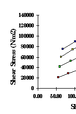
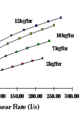
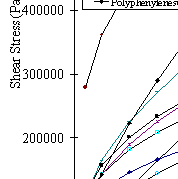
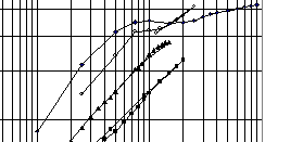
It is usual to plot shear stress vs shear rate first, as shown in Figure 3, before going on to plot the shear viscosity vs shear rate plot of figure 1. Figure 3 shows the shear stress functions of a range of polymers. Shear stress and shear rate are functions of die pressure drop and flow rate respectively. Consequently, the shape of this plot will be similar to that of the actual process die pressure vs throughput, and it is immediately clear that the flow behaviour will be very different for each of these materials. Shear
viscosity sensitive to molecular architecture?
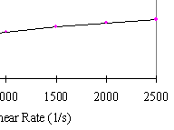
Changes in shear stress function due to changes in Mw can clearly be seen in Figure 4.
|
|
| The resulting shear stress functions have been created by the chemical chain extension of linear low density polyethylene (LLDPE). In this case the LLDPE was chain extended during reactive extrusion, the polymer was extruded at various throughputs with the constant addition of an organic peroxide dissolved in a carrier solvent. Pelletised extrudate was then tested on a capillary rheometer. At first the results appeared curious; since the peroxide proportion remained constant at each flow rate, it would be expected that the degree of chain extension be equal, however the viscosity rises in proportion with increasing flow rate. It was later discovered that at the lower flow rates, although the residence time was well in excess of the peroxide half life, mixing was poor and consequently reaction inefficient. On increasing the flow rate, and thus increasing the degree of fill within the extruder, mixing improved as did chain extension. |
|
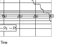
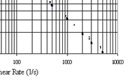
Shear viscosity as a melt fracture indicator Melt fracture manifests itself as poor product surface quality and is thus problematic in processes where surface integrity is important, of which film and pipe extrusion constitute two of the most prolific. In film extrusion even a loss of gloss can constitute the difference between good and reject product. Melt fracture can strike at production relevant throughputs, and with no easy fixes, has ensured it has not been discarded as an interesting pursuit for academics alone. Surface distortion in these products is no newcomer, but the cause of the distortion has, and continues to be, a much debated subject. Irrespective of the causes, some of the confusion surrounding melt fracture has been exacerbated, not least, by the abundance of terms used to describe the distortions themselves. The subject has been further complicated by debate over whether fracture is a die land length or exit phenomena. Regardless
of the mechanisms governing melt fracture, the reality of problematic
surface distortion continues, and once established is very difficult,
if not impossible, to eradicate. The benefit of capillary rheometry is
that melt fracture can be detected by conducting a shear viscosity sweep
over a range of shear rates, and once identified, some measures can be
taken to avoid it. |
|
Figure
5 Die
pressure fluctuations indicate melt fracture in HDPE
|
|||||||||
|
|
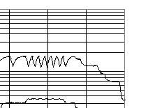
Figure 5 shows how melt fracture manifests itself as pressure fluctuations on the long die pressure trace of a twin bore rheometry test. These pressure fluctuations correspond to the initiation of visible extrudate surface distortion. Hatzikiriakos1 suggests that high stretching rates, due to melt accelerating as it attempts to catch up with the extrudate surface velocity on exiting the die, is the reason for the fracture. Conversely Ramamuthy2 and Kalika and Denn3 suggest that the phenomena is caused by adhesion failure in the die land length. Both camps however appear to agree that the first stage of distortion is termed sharkskin, and both show that wall slip is present in this region. This onset of melt fracture leading to sharkskin occurs at a critical shear stress that Ramamurthy shows to be independent of temperature, and molecular weight distribution (MWD). On examining the resulting shear stress vs shear rate plot of a melt fracturing material, it can also be seen that a slight change of slope occurs at the onset of sharkskin, which would be in keeping with the occurance of wall slip. Thereafter the distortions become severe leading to what Ramamurthy calls gross melt fracture and Kalika and Denn term wavy or stick-slip fracture. The curves then become almost rate independent as the pressure cycles as shown in Figure 5. It is often possible to increase the shear rate until the distortions end and effectively pass through a melt fracture window. |
|
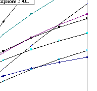
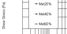
Figure
6
Melt Fracture
in blends of Metallocene and Ziegler-Nata catalysed LLDPE.
|
||||||||||||
|
|
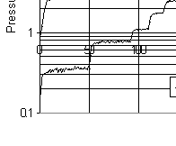
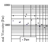
Figure 6 shows the shear stress functions of blends of Metallocene and Zeigler-Nata catalysed LLDPE. The materials were initially blended to reduce the viscosity of the pure Metallocene catalysed polymer. The virgin Metallocene curve shows the characteristic slope change on initiation of melt fracture and sharkskin in keeping with the above definitions. The critical shear stress appears to be in the region of 0.45MPa and a resulting shear rate of approximately 500s-1. A region of severe distortion or gross melt fracture is then entered before distortion ends at about 2000 s-1. On blending the Metallocene with the Ziegler-Nata catalysed polymer it can be seen that the shear viscosity drops as the proportion of Metallocene catalysed material reduces. However, the critical shear stress is also reducing, which in turn, elevates the shear rate at which melt fracture is initiated to over 2000s-1 in the 20% case. This is one of the few cases where the onset of melt fracture can be successfully manipulated. Without blending, it is often the output, die geometry and/or die material1,4 that has to be manipulated in order to traverse the shear stress vs shear rate curve to a distortion free zone. In the case of film blowing, die geometry changes often adversely affect bubble cooling rates and product mechanical properties. The ability
of viscosity function testing to identify the onset of melt fracture using
only a hand full of material can be of tremendous benefit when in many
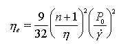
cases melt fracture is discovered once it is too late. So far the definition of viscosity used has been restricted to that of shear, in which material flow is envisaged as laminates of fluid sliding past each other having zero velocity at the wall and some maximum value at the centre of the capillary. Elongational flow can be envisaged as the stretching of a polymer element from one original length to some final length over a specified time period. Expressions of stress and strain rate can be established by a knowledge of the change in element geometry and the forces involved during extension. When calculating shear viscosity via the Poiseuille flow equations the energy dissipated in overcoming the resistance to elongation is generally dwarfed by the shear contribution. Both the trend and absolute calculation of elongational viscosity can often be sensitive to changes in polymer structure, in particular MWD, which are hithertoo invisible to shear viscosity. There are various methods by which elongational viscosity can be deduced5,6,7,8, this paper however uses the Cogswell9 convergent flow model. The method developed by Cogswell exploits the fact that polymer flowing through an abrupt contraction has a significant extensional component where, |
|
Elongational
Viscosity
|
|
 |
(1) |
|
and n is the power law index, Po the entrance pressure drop, h the shear viscosity and g the shear rate. Clearly the dominant parameter is the entrance pressure drop, Po which is that pressure measured prior to entry of an orifice die, and is dominated by elongational flow. The following
example endeavours to demonstrate the sensitivity of elongational viscosity
measurements to rheological and molecular phenomena otherwise invisible
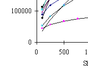
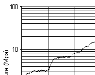
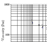
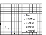
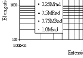
to shear viscosity and melt flow index (MFI) measurements. Cross-linking of the olefin family has been used extensively for the enhancement of physical properties such as elevated melting point, improvements in stress cracking, solvent resistance10, service life and dimensional stability. The techniques used to induce cross-linking are usually chemical, via organic peroxides11 thermal or radiation12, each having its own unique benefit and limitation. LLDPE is usually cross-linked via the free radical, organic peroxide route13 but some producers use radioactive means. Irrespective of the means, determining the exact degree of cross-linking, and thus characterisation, can be difficult. The usual methods employed to determine degree of cross-linking are either Gel Permeation Chromatography (GPC) or gel content measurement. Both techniques can suffer experimental difficulty and error, often due to the small degrees of cross-linking involved. Figure 7 shows the shear viscosity functions of a radiation cross-linked LLDPE. Five functions are plotted together on the graph representing irradiation levels of 0, 0.25, 0.5, 0.75 and 1.0MRad. Clearly no distinction can be made between samples and this was, as expected, the case with MFI, however very clear production behaviour was observed. Figure 8 shows the plot of elongational viscosity vs extensional stress for the various irradiation levels and it can be seen that very clear distinction is possible. |
|
Figure
7 Radiation
cross-linked LLDPE; Shear viscosity is insensitive to irradiation level.
|
Figure 8 Elongational viscosity functions infer MWD manipulation via irradiation | ||||||||||||||||||
|
|
|
Since the shear viscosity and MFI results show no clear distinction, it would be reasonable to suspect that the Mw for each of the samples is similar, but that the MWD is changing. It is suspected that the radiation cross-linking is acting to broaden the MWD, and thus increase the proportion of long chain molecules, whilst retaining similar . Whilst absolute values of the degree of cross-linking could not be obtained in this case, correlation via elongational viscosity proved to be very sensitive to change. |
|
FLOW SIMULATION So far we
have seen how the measurement of viscosity can be used to produce flow
curves for the purposes of differentiating materials and gaining an insight
into molecular architecture. However, flow data can also be used in flow
simulation, whereby we recreate a flow geometry and predict the likely
consequences. These flow geometries are of course more usefully those
found in real process dies, and as such we can begin to simulate the consequences
of changing variables such as temperature, flow rate, material and even
geometry itself in order to optimise the process without resorting to
costly pilot plant trials. It is often best to start by gaining a feel
for the prediction accuracy by applying a viscosity function to a simulated
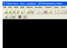
rheometer die geometry. Figure 9 shows the simulated pressure distribution
in a typical 16mm long, 1mm diameter capillary rheometer die. The simulation
uses Compuplast Flow2D, and represents an axis symmetric view; that is
only half of the die is seen about its centre line. |
|
Figure
9 Simulated capillary
rheometer die showing predicted pressure distribution
|
||||||||||||||||
|
|
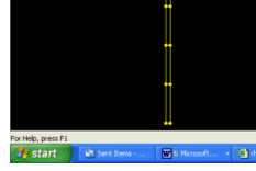
In order to run this simulation the viscosity function produced on the rheometer has to be entered into the simulation package data base. It is then fitted with, in this case, the Carreau model. Three viscosity functions have been fitted at three different temperatures in order to allow temperature shifting. The fitting procedure also requires the input of the following thermal data; thermal conductivity (K), specific heat capacity (Cp), solid and melt density, heat of fusion, freezing point and melt temperature. Once these properties have been input, the geometry is assigned the various boundary conditions. |
|
Figure
10 Geometry of
die and barrel comprised of nodes and boundaries
|
||||||||||||||||
|
|
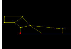
Figure 10 shows how the mesh appears in the geometry editor. The external boundaries describe the barrel and die walls, and as such are assigned the temperature at which the test was conducted. The red boundary at the top of the mesh is assigned to the input as a mass flow rate, the bottom being the output. The benefit of simulating the rheometer die is that we already know what the developed pressure was and can thus compare it directly with the prediction in order to gain a feel for accuracy. Cable coating Clearly the more complex process dies are of ultimate interest if we are to truly benefit from flow simulation. Figure 11 shows the geometry mesh of a cable coating die, the lower red boundary being that of the wire in this case. The wire is subsequently assigned the velocity and temperature it would have in reality, with the remaining walls being those of the wire guide and die. The chosen material and flow rates are then entered and the simulation run. |
|
Figure
11 Geometry of
a cable coating die
|
||||||||||||||||
|
|
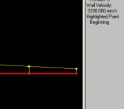
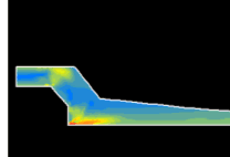
Figures 12 & 13 show the solved simulation, in this case focusing on the predicted shear stresses. Once solved velocity, shear rate, temperature, pressure and a host of other parameters can be examined. |
|
Figure
12 Shear stress
distribution in a cable coating die
|
||||||||||||||||
|
|
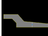
Figure
13 Cuts through
a specific section of the die showing predicted shear stress
|
||||||||||||||||
|
|
It is known that in this case melt fracture is a problem using the assigned coating material. By simulating different flow rates, wire speeds, and wire guide geometries, it has been possible to optimise the shear stress distribution in order to avoid melt fracture, and thus unwanted surface distortion.
It is hoped from the work presented in this paper that the reader can gain an appreciation of some of the rheological tools available via capillary rheometry. In particular it is often the way in which a polymer resists deformation that can provide a valuable insight into its molecular architecture and the likely consequences on product integrity. It is also clear that flow simulation is already capable of accurately predicting the flow behaviour of complex polymer melts in real dies. In the future it is expected that the accuracy and scope of simulation will expand sufficiently to enable the prediction of die swell and melt fracture to name but two particularly problematic phenomena. |
|
References [1] Hatzikiriakos,
S.G., Polym. Eng. & Sci., 34 (19) 1441 (1994). |
|
View the original Paper presentation in PDF format here: |
File
Size: 148Kb
|